 |
|||
|
Introduction
Product Description
Free Trial
Tutorials
Testimonials
Buy It!
Support
Contact Us
Feedback
|
Model System Dynamics with Block Diagrams
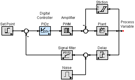
Express dynamics visually for easier understandingVisual representations can reduce the mystery of dynamical systems. These systems are often described by ordinary differential equations. For linear systems, the differential equation can be transformed into an algebraic equation by using the Laplace transform (s-domain). Digital controllers sample continuous systems. The equations in a controller can be described by difference equations (z-domain or z-transform). Many non-linear effects such as saturation, hysteresis or friction are important to consider in practical applications. SimApp can model all of these effects in a single visual block diagram. Achieve more robust designs with SimAppSimApp can be used to examine the time response or the frequency response of the dynamic system once the model is built. The effect of parameter variations can be quickly examined. The designer then may specify component changes without buying expensive prototypes. Opportunities to relax tolerances can result in lower costs. Design cycles can be shortened by testing controller design ideas.
| ||
| About Us | Contact Us | Privacy Policy | |||
